![ATI: Super Damper Crank Balancer [Camaro ZL1 gen 6, CTS V gen 3, LT4]](http://weaponxmotorsports.com/cdn/shop/products/ati-918856_grande.jpg?v=1571441785)
![ATI: Super Damper Crank Balancer [Camaro ZL1 gen 6, CTS V gen 3, LT4]](http://weaponxmotorsports.com/cdn/shop/products/ati-918856_1024x1024.jpg?v=1571441785)

More info
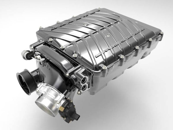
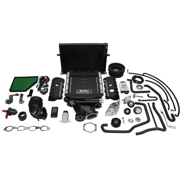
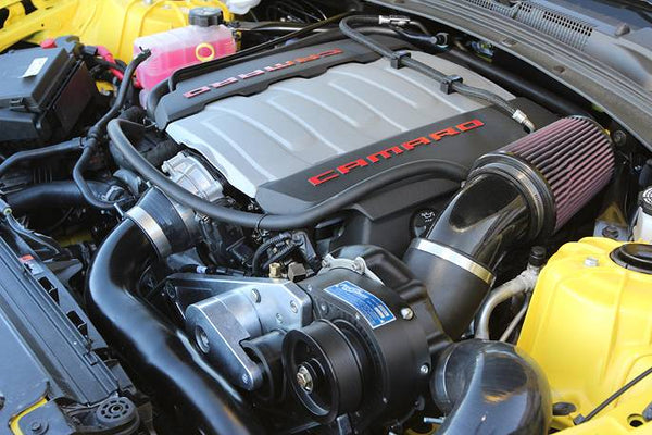
2016+ LT1 CAMARO SS & LT4 CAMARO ZL1 & LT4 CADILLAC CTS V ![]()
Options: Choose from none up to a 21.5% ring to overdrive your supercharger!
The patented ATI Super Damper is the only crankshaft damper designed exclusively for high performance Chevy engines.
- Eliminates torsional crankshaft vibrations
- Exceeds SFI 18.1 specs
- Black zinc chromate finished
- OEM equipment on ZZ572 GM Crate Engines
- Tunable, rebuildable, and extremely efficient at ALL RPM
- Laser engraved 360° timing marks
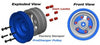
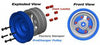
Inner and outer shells are available in aluminum or steel, and contain a steel inertia weight. This inertia weight has six (2-ring design) or eight (3-ring design) computer machined grooves to retain the proper durometer O-rings (dyno tested for each application).
| ATI Super Damper Installation Instructions |
![]()
- DAMPER ASSEMBLY MUST NOT BE DRILLED TO BALANCE. THE ASSEMBLY IS FULLY MACHINE-BALANCED AND MUST NOT BE ALTERED.
Zero balance units have each part individually balanced to two-tenths of a gram. These units should not be drilled and should not be on the crankshaft for balancing. Install the damper at engine assembly. Since the inertia weight in the Super Damper is not bonded, it may not be on center until the engine is started. The damper may show out of balance until the engine reaches 2000 RPM the first time and the inertia weight centers itself.
ATI dampers must be retained to the crank with a standard length bolt torqued to the manufacturer's specifications. Longer bolts used to retain drive mandrels stretch when they get hot and should not be used. ATI manufactures special hubs for many engines to put the bolt below flush and allow drive mandrels to be located and bolted to the 3 pulley bolt holes. Mandrels are drilled and tapped to retain pulleys and dry sump drives. Mandrels, pulleys and accessory drives are available from ATI (800-284-3433), BLP Products (800-624-1358), CV Products (800-448-1223), Moroso (203-453-6571), Peterson Fluid Systems (800-926-7867), and Jones Belt Drives (610-847-2028). ATI can duplicate your existing long bolt drives to bolt-on mandrel type in one week without plating.
Press fit of the hub to the crankshaft is vital to transfer harmonics to the damper assembly. Recommended press is as follows:
|
Crankshaft Snout Diameter
|
Recommended interference
|
|
1.0000" - 1.2500"
|
.0009" to .0012"
|
|
1.2510" - 1.3750"
|
.0008" to .0011"
|
|
1.3750" - 1.6000"
|
.0007" to .0009"
|
GM cranks are typically to tolerance +/- .0001". If you are using an OEM GM crank you can hone the damper hub as follows:
|
|
hone to 1.5993" +/- .0001" |
|
|
hone to 1.2460" +/- .0001" |
On all other cranks, the crank must be checked with micrometers and the hub with a dial bore gauge to verify fit. Most OEM cranks are held to +/- .0002" while most aftermarket cranks are held to +/- .0005." Hub bores are tight to accommodate aftermarket cranks and most steel hubs will require honing. Do not hone aluminum hubs.
NOTE: If using a front cover teflon seal, you must use a “Speedy Sleeve” or a steel hub.
Aluminum hubs have a .002” press fit between the crank and the hub. DO NOT ALTER the press fit of the hub in any way! The press fit on the aluminum hub is slightly tighter to compensate for the elasticity of the aluminum.
To install, heat the hub in boiling water for five minutes to expand the hub slightly and help it slide onto the crank. Use gloves to handle the hub after it has been heated. After installing the hub, allow time for it to cool.
Installation![]()
Tools needed:
- Damper installation tool
- Torx T-40 Plus bit
- Torx T-45 Plus bit
- 3/8" 12pt socket
|
If you are installing one of the following dampers:
|
||||
| P/N: 917060 | P/N: 917062 | P/N: 917080 | P/N: 917740 | P/N: 917780 |
| P/N: 917781 | P/N: 917788 | P/N: 918598 | P/N: 918599 | |
|
DO NOT disassemble the damper for installation. Install as a complete damper! |
||||
Assembling the damper to the hub:
NOTE: The hub to damper fit is held to an extremely close tolerance!
1. Align the indent dimples on the hub and damper. The indent dimple on the damper is marked by the offset hole arrow on the damper decal.
2. Start three 12-point bolts in front of the damper in the three holes that are not countersunk. Use 242 Loctite (blue). Do not pull down tight on the damper!
3. Start the six (6) countersunk flathead screws in the remaining six holes. Use Loctite 242 on these six screws. Draw the damper assembly onto the hub evenly. Torque the 3 12-point screws to 30 ft./lbs. They must be installed and torqued even if no pulleys are used.
4. Torque the 6 flathead screws to 16 ft./lbs.
5. For 5 1/2" dampers, the six 1/4-20/28 bolts must be torqued to 120 in/lbs and Loctite used.
Installing the Damper and Hub assembly to the crankshaft:
1. Inspect your crankshaft for burrs, nicks and imperfections and file them down.
2. Stone or file a slight radius on end of the crankshaft snout to break the sharp edge.
3. Inspect your key and replace if necessary.
4. Apply anti-seize lubricant on the crankshaft before hub installation.
5. Press the Damper & Hub assembly onto the crankshaft. If you wish to install the hub onto the crankshaft first, use the proper puller installer.
6 . Install the crank bolt and torque to the manufacturer's specifications. Longer bolts used to retain drive mandrels stretch when they get hot and should not be used.
7. Set the damper to desired timing position. The zero timing mark is keyed exactly as the OEM part.
• Street / Strip (Up to 800 HP) drag use should be checked every 10 years. Sportsman drag race engines subject the damper to low total cycles at intermittent intervals. Elastomer in all units 6" and larger diameter dampers should be checked every 10 years.
• Pro & Fuel Drag Use will vary depending on class and power levels. Dampers should be inspected annually.
• Circle track & endurance racing applications: Damper and o-rings should be inspected with each engine rebuild. Circle track engines subject the damper to greatly increased cycle times for an extended period of time and the damper requires more attention. Most Nextel Cup teams are inspecting rubber after each race or every 2 races (1.2 to 2.5 million cycles). Engines running shorter races can easily go 2.5 million cycles.
• 5.5" Dampers found on most import engines should follow the following maintenance schedule:
|
Engine HP
|
Recommended Maintenance
|
|
Over 600 HP
|
yearly
|
|
400-600 HP
|
2 to 3 years
|
|
Up to 400 HP
|
5 years
|
Should you need to return your Super Damper for any reason; overhaul, repair, etc., please call ATI at 410-298-4343 or 800-284-3433 to receive your Returned Goods Authorization (RGA) number.
![WEAPON-X: 112mm Throttle Body Adapter [LS LT1 LT4]](http://weaponxmotorsports.com/cdn/shop/products/image_b97bf8f9-aa0d-4e29-b70c-75aa38199a79_grande.jpg?v=1571441896)
![WEAPON-X: 112mm Throttle Body Adapter [LS LT1 LT4]](http://weaponxmotorsports.com/cdn/shop/products/image_769c292c-1378-47aa-bd84-d19b4906ac89_small.jpg?v=1571441896)
![WEAPON-X: 112mm Throttle Body Adapter [LS LT1 LT4]](http://weaponxmotorsports.com/cdn/shop/products/image_f6698a85-114e-4bb6-9d58-b501375fc993_small.jpg?v=1571441896)
![WEAPON-X: 112mm Throttle Body Adapter [LS LT1 LT4]](http://weaponxmotorsports.com/cdn/shop/products/image_06828d4e-cc00-44ff-8f39-0ca65765899c_small.jpg?v=1571441896)
![WEAPON-X: 112mm Throttle Body Adapter [LS LT1 LT4]](http://weaponxmotorsports.com/cdn/shop/products/image_b789ceec-2a56-4ee9-8e49-85d626d7234e_small.jpg?v=1571441896)
![WEAPON-X: 112mm Throttle Body Adapter [LS LT1 LT4]](http://weaponxmotorsports.com/cdn/shop/products/image_033842d1-063f-49e8-b9a6-76f622111c68_small.jpg?v=1571441896)
![WEAPON-X: 112mm Throttle Body Adapter [LS LT1 LT4]](http://weaponxmotorsports.com/cdn/shop/products/image_f69e074e-1605-4bd9-9d09-3ff15792bbba_small.jpg?v=1571441896)
![WEAPON-X: Lower Pulley Kit [CTS V gen 3, Camaro ZL1 gen 6, LT4]](http://weaponxmotorsports.com/cdn/shop/products/ICP-LSA-14_large_5_e78a6ae3-ef75-4af4-bdd1-75fef752f102_grande.jpg?v=1571441592)
![WEAPON-X: Lower Pulley Kit [CTS V gen 3, Camaro ZL1 gen 6, LT4]](http://weaponxmotorsports.com/cdn/shop/products/SD-HUB-300w_small.jpg?v=1571441592)
![WEAPON-X: Lower Pulley Kit [CTS V gen 3, Camaro ZL1 gen 6, LT4]](http://weaponxmotorsports.com/cdn/shop/products/840-1000_2_small.jpg?v=1571441592)
![WEAPON-X: Lower Pulley Kit [CTS V gen 3, Camaro ZL1 gen 6, LT4]](http://weaponxmotorsports.com/cdn/shop/products/CTS-VCrankPulleyRings-5_large_1_abe53de9-9111-4b84-bac5-22808b43dd80_small.jpg?v=1571441592)
![WEAPON-X: Lower Pulley Kit [CTS V gen 3, Camaro ZL1 gen 6, LT4]](http://weaponxmotorsports.com/cdn/shop/products/ICP-LSA-15_large_1_b1631e44-db02-4c40-83a3-9c91859640c2_small.jpg?v=1571441592)
![WEAPON-X: Lower Pulley Kit [CTS V gen 3, Camaro ZL1 gen 6, LT4]](http://weaponxmotorsports.com/cdn/shop/products/ICP-LSA-16_large_1_ced27a6b-979f-471a-ae21-dc9651816ac8_small.jpg?v=1571441592)
![WEAPON-X: LT4 Supercharger Conversion [C7 Corvette, Camaro gen 6]](http://weaponxmotorsports.com/cdn/shop/products/lt4kit1_grande.jpg?v=1571441529)
![WEAPON-X: LT4 Supercharger Conversion [C7 Corvette, Camaro gen 6]](http://weaponxmotorsports.com/cdn/shop/products/IMG_0833_1024x1024_576876ec-153c-41df-a1e7-bf88e3a95f3c_small.jpg?v=1569297747)
![WEAPON-X: LT4 Supercharger Conversion [C7 Corvette, Camaro gen 6]](http://weaponxmotorsports.com/cdn/shop/products/lt4_stingray_small.jpg?v=1571441529)
![WEAPON-X: LT4 Supercharger Conversion [C7 Corvette, Camaro gen 6]](http://weaponxmotorsports.com/cdn/shop/products/IMG_0832_1024x1024_2c2d267f-7a0f-4afd-92fe-d633f8238ea3_small.jpg?v=1569297747)
![WEAPON-X: LT4 Supercharger Conversion [C7 Corvette, Camaro gen 6]](http://weaponxmotorsports.com/cdn/shop/products/lt4_stingray2_small.jpg?v=1571441529)
![WEAPON-X: LT4 Supercharger Conversion [C7 Corvette, Camaro gen 6]](http://weaponxmotorsports.com/cdn/shop/products/IMG_0200_1024x1024_34c9c67b-ce7d-42b8-9734-9ebb2eb93d68_small.jpg?v=1569297747)
![WEAPON-X: LT4 Supercharger Conversion [C7 Corvette, Camaro gen 6]](http://weaponxmotorsports.com/cdn/shop/products/lt4kit2_small.jpg?v=1571441529)
![WEAPON-X: LT4 Supercharger Conversion [C7 Corvette, Camaro gen 6]](http://weaponxmotorsports.com/cdn/shop/products/lt4kit4_small.jpg?v=1571441529)
![WEAPON-X: LT4 Supercharger Conversion [C7 Corvette, Camaro gen 6]](http://weaponxmotorsports.com/cdn/shop/products/lt4kit3_small.jpg?v=1571441529)
![WEAPON-X: LT4 Supercharger Conversion [C7 Corvette, Camaro gen 6]](http://weaponxmotorsports.com/cdn/shop/products/lt4_stingray_3_dyno_small.jpg?v=1571441529)
![WEAPON-X: LT4 Supercharger Conversion [C7 Corvette, Camaro gen 6]](http://weaponxmotorsports.com/cdn/shop/products/IMG_0892a_1024x1024_a8886c05-c102-4a19-832a-52d0278ad088_small.jpg?v=1569297747)
![WEAPON-X: LT4 Cooling Manifold Adapters [C7 Corvette Z06, Camaro ZL1, CTS V3, LT4]](http://weaponxmotorsports.com/cdn/shop/products/IMG_9733_grande.JPG?v=1602597357)
![WEAPON-X: LT4 Cooling Manifold Adapters [C7 Corvette Z06, Camaro ZL1, CTS V3, LT4]](http://weaponxmotorsports.com/cdn/shop/products/IMG_0201_small.JPG?v=1602597357)
![WEAPON-X: LT4 Cooling Manifold Adapters [C7 Corvette Z06, Camaro ZL1, CTS V3, LT4]](http://weaponxmotorsports.com/cdn/shop/products/IMG_0892a_small.jpg?v=1602597357)
![WEAPON-X: LT4 Cooling Manifold Adapters [C7 Corvette Z06, Camaro ZL1, CTS V3, LT4]](http://weaponxmotorsports.com/cdn/shop/products/IMG_0731_d3b01fa9-5e52-4622-a1d1-7e01a968e2d0_small.JPG?v=1602597357)
![WEAPON-X: LT4 Cooling Manifold Adapters [C7 Corvette Z06, Camaro ZL1, CTS V3, LT4]](http://weaponxmotorsports.com/cdn/shop/products/1E94C448-8E74-42FD-8771-851C30985F22_small.JPG?v=1602597357)
![WEAPON-X: LT4 Cooling Manifold Adapters [C7 Corvette Z06, Camaro ZL1, CTS V3, LT4]](http://weaponxmotorsports.com/cdn/shop/products/IMG_0200_small.JPG?v=1602597357)
![WEAPON-X: LT4 Cooling Manifold Adapters [C7 Corvette Z06, Camaro ZL1, CTS V3, LT4]](http://weaponxmotorsports.com/cdn/shop/products/IMG_0202_small.JPG?v=1571441785)
![WEAPON-X: LT4 Cooling Manifold Adapters [C7 Corvette Z06, Camaro ZL1, CTS V3, LT4]](http://weaponxmotorsports.com/cdn/shop/products/IMG_0203_small.JPG?v=1571441785)
![WEAPON-X: LT4 Cooling Manifold Adapters [C7 Corvette Z06, Camaro ZL1, CTS V3, LT4]](http://weaponxmotorsports.com/cdn/shop/products/IMG_0378_small.JPG?v=1571441785)
![WEAPON-X: LT4 Cooling Manifold Adapters [C7 Corvette Z06, Camaro ZL1, CTS V3, LT4]](http://weaponxmotorsports.com/cdn/shop/products/IMG_0832_small.JPG?v=1571441785)
![WEAPON-X: LT4 Cooling Manifold Adapters [C7 Corvette Z06, Camaro ZL1, CTS V3, LT4]](http://weaponxmotorsports.com/cdn/shop/products/IMG_0833_small.JPG?v=1571441785)
![WEAPON-X: LT4 Cooling Manifold Adapters [C7 Corvette Z06, Camaro ZL1, CTS V3, LT4]](http://weaponxmotorsports.com/cdn/shop/products/IMG_0834_small.JPG?v=1571441785)
![WEAPON-X: LT4 Cooling Manifold Adapters [C7 Corvette Z06, Camaro ZL1, CTS V3, LT4]](http://weaponxmotorsports.com/cdn/shop/products/LT4_adapters_installed_small.jpg?v=1571441785)
![DSX: Baro IAT Breakout Harness Gen V [Camaro, Corvette, CTS V, LT1 LT4 LT5]](http://weaponxmotorsports.com/cdn/shop/products/C7BOH_1800x_d5c7d93c-27d2-4884-b570-cd4d57d79bf9_grande.jpg?v=1571441395)
![WEAPON-X SPI Kit: Secondary Port Injection [Camaro, Corvette, CTS V, LT1 LT4]](http://weaponxmotorsports.com/cdn/shop/products/20201030_125315_1_grande.jpg?v=1604082928)
![WEAPON-X SPI Kit: Secondary Port Injection [Camaro, Corvette, CTS V, LT1 LT4]](http://weaponxmotorsports.com/cdn/shop/products/2018-05-11_13.15.53_small.jpg?v=1604082928)
![WEAPON-X SPI Kit: Secondary Port Injection [Camaro, Corvette, CTS V, LT1 LT4]](http://weaponxmotorsports.com/cdn/shop/products/IMG_20200124_160741_565_small.jpg?v=1604082928)
![WEAPON-X SPI Kit: Secondary Port Injection [Camaro, Corvette, CTS V, LT1 LT4]](http://weaponxmotorsports.com/cdn/shop/products/2018-04-29_21.15.26_small.jpg?v=1604082928)
![WEAPON-X SPI Kit: Secondary Port Injection [Camaro, Corvette, CTS V, LT1 LT4]](http://weaponxmotorsports.com/cdn/shop/products/20180702_174053_small.jpg?v=1604082928)
![WEAPON-X SPI Kit: Secondary Port Injection [Camaro, Corvette, CTS V, LT1 LT4]](http://weaponxmotorsports.com/cdn/shop/products/image1_small.jpeg?v=1604082928)
![WEAPON-X SPI Kit: Secondary Port Injection [Camaro, Corvette, CTS V, LT1 LT4]](http://weaponxmotorsports.com/cdn/shop/products/Reigsecker_1_small.jpg?v=1604082928)
![WEAPON-X SPI Kit: Secondary Port Injection [Camaro, Corvette, CTS V, LT1 LT4]](http://weaponxmotorsports.com/cdn/shop/products/IMG_3241_small.JPG?v=1604082928)
![WEAPON-X SPI Kit: Secondary Port Injection [Camaro, Corvette, CTS V, LT1 LT4]](http://weaponxmotorsports.com/cdn/shop/products/IMG_3824_small.JPG?v=1604082928)
![WEAPON-X SPI Kit: Secondary Port Injection [Camaro, Corvette, CTS V, LT1 LT4]](http://weaponxmotorsports.com/cdn/shop/products/IMG_3388_small.JPG?v=1604082928)
![WEAPON-X SPI Kit: Secondary Port Injection [Camaro, Corvette, CTS V, LT1 LT4]](http://weaponxmotorsports.com/cdn/shop/products/IMG_3386_small.JPG?v=1604082928)
![WEAPON-X SPI Kit: Secondary Port Injection [Camaro, Corvette, CTS V, LT1 LT4]](http://weaponxmotorsports.com/cdn/shop/products/20180702_174103_small.jpg?v=1604082928)
![WEAPON-X SPI Kit: Secondary Port Injection [Camaro, Corvette, CTS V, LT1 LT4]](http://weaponxmotorsports.com/cdn/shop/products/2018-06-28_17.09.46_small.jpg?v=1604082928)
![WEAPON-X SPI Kit: Secondary Port Injection [Camaro, Corvette, CTS V, LT1 LT4]](http://weaponxmotorsports.com/cdn/shop/products/2018-05-25_09.38.09_small.jpg?v=1604082928)
![WEAPON-X SPI Kit: Secondary Port Injection [Camaro, Corvette, CTS V, LT1 LT4]](http://weaponxmotorsports.com/cdn/shop/products/IMG_3330_small.JPG?v=1604082928)
![WEAPON-X SPI Kit: Secondary Port Injection [Camaro, Corvette, CTS V, LT1 LT4]](http://weaponxmotorsports.com/cdn/shop/products/2018-06-22_10.32.38_small.jpg?v=1604082928)
![WEAPON-X SPI Kit: Secondary Port Injection [Camaro, Corvette, CTS V, LT1 LT4]](http://weaponxmotorsports.com/cdn/shop/products/2018-05-11_16.50.35_small.jpg?v=1604082928)
![WEAPON-X SPI Kit: Secondary Port Injection [Camaro, Corvette, CTS V, LT1 LT4]](http://weaponxmotorsports.com/cdn/shop/products/IMG_3334_small.JPG?v=1604082928)
![WEAPON-X SPI Kit: Secondary Port Injection [Camaro, Corvette, CTS V, LT1 LT4]](http://weaponxmotorsports.com/cdn/shop/products/IMG_3253_small.JPG?v=1604082928)
![WEAPON-X SPI Kit: Secondary Port Injection [Camaro, Corvette, CTS V, LT1 LT4]](http://weaponxmotorsports.com/cdn/shop/products/IMG_3548_small.JPG?v=1604082928)
![WEAPON-X SPI Kit: Secondary Port Injection [Camaro, Corvette, CTS V, LT1 LT4]](http://weaponxmotorsports.com/cdn/shop/products/2018-05-01_15.04.48_small.jpg?v=1604082928)
![WEAPON-X SPI Kit: Secondary Port Injection [Camaro, Corvette, CTS V, LT1 LT4]](http://weaponxmotorsports.com/cdn/shop/products/20200117_130054_small.jpg?v=1604082928)
![WEAPON-X: Whipple Griptec Pulley [Camaro Corvette CTS V, LT1 LT4 LT5]](http://weaponxmotorsports.com/cdn/shop/products/image1_1_0254f50f-b7bc-4a50-8cfa-32aef2e3d8d9_grande.jpg?v=1571441528)
![WEAPON-X: Procharger Griptec Pulley [Camaro6, Corvette C7, LT1 LT4]](http://weaponxmotorsports.com/cdn/shop/products/6A5A4092_grande.jpg?v=1571441785)
![WEAPON-X: Procharger Griptec Pulley [Camaro6, Corvette C7, LT1 LT4]](http://weaponxmotorsports.com/cdn/shop/products/6A5A4099_small.jpg?v=1571441785)
![WEAPON-X: Procharger Griptec Pulley [Camaro6, Corvette C7, LT1 LT4]](http://weaponxmotorsports.com/cdn/shop/products/6A5A4104_small.jpg?v=1571441785)
![WEAPON-X: Procharger Griptec Pulley [Camaro6, Corvette C7, LT1 LT4]](http://weaponxmotorsports.com/cdn/shop/products/6A5A4105_small.jpg?v=1571441785)
![WEAPON-X: Big Gulp DI Fuel Package [Camaro Corvette CTS V, LT1 LT4 LT5]](http://weaponxmotorsports.com/cdn/shop/products/hrdp-1302-04_2014-chevrolet-lt1-v8-engine_direct-injection-system_grande_ab02a37b-94ed-4865-a544-9603435743f7_grande.jpg?v=1571441528)
![WEAPON-X: Big Gulp DI Fuel Package [Camaro Corvette CTS V, LT1 LT4 LT5]](http://weaponxmotorsports.com/cdn/shop/products/FIC_9470cc2b-62e6-473d-9be6-b842d443cc59_small.jpg?v=1571441528)
![WEAPON-X: Big Gulp DI Fuel Package [Camaro Corvette CTS V, LT1 LT4 LT5]](http://weaponxmotorsports.com/cdn/shop/products/IMG_8654_4ddb92f9-1ede-4e2f-b1bf-8cf7147fd69f_small.jpg?v=1571441528)
![WEAPON-X: Big Gulp DI Fuel Package [Camaro Corvette CTS V, LT1 LT4 LT5]](http://weaponxmotorsports.com/cdn/shop/products/IMG_8662_f2a0677a-4805-4f1b-ac11-cc8254e99372_small.jpg?v=1571441528)
![WEAPON-X: Big Gulp DI Fuel Package [Camaro Corvette CTS V, LT1 LT4 LT5]](http://weaponxmotorsports.com/cdn/shop/products/lpe_5dffebb4-616c-4f48-8605-2a6a35fc22a3_small.jpg?v=1571441528)
![WEAPON-X: Big Gulp DI Fuel Package [Camaro Corvette CTS V, LT1 LT4 LT5]](http://weaponxmotorsports.com/cdn/shop/products/lt1-lt4-driect-injection-engine-08_grande_dd84318e-6e39-4eed-afdf-e970f5670933_small.jpg?v=1571441528)
![WEAPON-X: Whipple LT1 LT4 Cooling Adapters [Camaro Corvette CTS V, LT]](http://weaponxmotorsports.com/cdn/shop/products/image_9b97fe76-8750-465b-879a-0cf66b6345e7_grande.jpg?v=1571441896)
![WEAPON-X: Whipple LT1 LT4 Cooling Adapters [Camaro Corvette CTS V, LT]](http://weaponxmotorsports.com/cdn/shop/products/image_0e81af22-d0a3-4605-a87d-2b2153c0fe95_small.jpg?v=1571441896)
![WEAPON-X: Griptec Magnuson Pulley [Camaro6, Corvette C7, LT1 LT4]](http://weaponxmotorsports.com/cdn/shop/files/6A5A4092_de052dba-ec56-4970-9c89-d35eace43bb6_grande.jpg?v=1714422121)
![WEAPON-X: Griptec Magnuson Pulley [Camaro6, Corvette C7, LT1 LT4]](http://weaponxmotorsports.com/cdn/shop/files/6A5A4099_56409198-da16-487b-ab1c-0e50d66407de_small.jpg?v=1714422122)
![WEAPON-X: Griptec Magnuson Pulley [Camaro6, Corvette C7, LT1 LT4]](http://weaponxmotorsports.com/cdn/shop/files/6A5A4104_a46d173d-79b9-457d-b390-243f1136de77_small.jpg?v=1714422122)
![WEAPON-X: Griptec Magnuson Pulley [Camaro6, Corvette C7, LT1 LT4]](http://weaponxmotorsports.com/cdn/shop/files/6A5A4105_476de359-3974-4b1d-99e4-d775bf8e74a4_small.jpg?v=1714422123)
![WEAPON-X: Griptec Edelbrock Pulley [Camaro6, Corvette C7, LT1 LT4]](http://weaponxmotorsports.com/cdn/shop/products/6A5A4092_de052dba-ec56-4970-9c89-d35eace43bb6_grande.jpg?v=1571441896)
![WEAPON-X: Griptec Edelbrock Pulley [Camaro6, Corvette C7, LT1 LT4]](http://weaponxmotorsports.com/cdn/shop/products/6A5A4099_56409198-da16-487b-ab1c-0e50d66407de_small.jpg?v=1571441896)
![WEAPON-X: Griptec Edelbrock Pulley [Camaro6, Corvette C7, LT1 LT4]](http://weaponxmotorsports.com/cdn/shop/products/6A5A4104_a46d173d-79b9-457d-b390-243f1136de77_small.jpg?v=1571441896)
![WEAPON-X: Griptec Edelbrock Pulley [Camaro6, Corvette C7, LT1 LT4]](http://weaponxmotorsports.com/cdn/shop/products/6A5A4105_476de359-3974-4b1d-99e4-d775bf8e74a4_small.jpg?v=1571441896)