![WEAPON-X: Eaton 1.7L Lid Spacer - Meth or Nitrous Options [Camaro Corvette CTS V, LT4]](http://weaponxmotorsports.com/cdn/shop/products/image1_6a4dba5c-0431-4843-b346-e46c9dc6025b_grande.jpg?v=1571441394)
![WEAPON-X: Eaton 1.7L Lid Spacer - Meth or Nitrous Options [Camaro Corvette CTS V, LT4]](http://weaponxmotorsports.com/cdn/shop/products/image1_6a4dba5c-0431-4843-b346-e46c9dc6025b_1024x1024.jpg?v=1571441394)
![WEAPON-X: Eaton 1.7L Lid Spacer - Meth or Nitrous Options [Camaro Corvette CTS V, LT4]](http://weaponxmotorsports.com/cdn/shop/products/image2_175e7879-ff74-4a87-b447-ef69ce78f396_1024x1024.jpg?v=1571441394)
![WEAPON-X: Eaton 1.7L Lid Spacer - Meth or Nitrous Options [Camaro Corvette CTS V, LT4]](http://weaponxmotorsports.com/cdn/shop/products/cts_v_alky_control_1024x1024_4b12a509-0502-47a1-86c5-3552ed942f58_1024x1024.jpg?v=1571441394)
![WEAPON-X: Eaton 1.7L Lid Spacer - Meth or Nitrous Options [Camaro Corvette CTS V, LT4]](http://weaponxmotorsports.com/cdn/shop/products/photo_3__44468.1353812148.1280.1280_1024x1024_09662445-0de5-43d8-9fc0-331741bfdc35_1024x1024.jpg?v=1571441394)
![WEAPON-X: Eaton 1.7L Lid Spacer - Meth or Nitrous Options [Camaro Corvette CTS V, LT4]](http://weaponxmotorsports.com/cdn/shop/products/image_1024x1024_5515e871-a38f-47a6-8b65-0b1463df3632_1024x1024.jpg?v=1571441394)
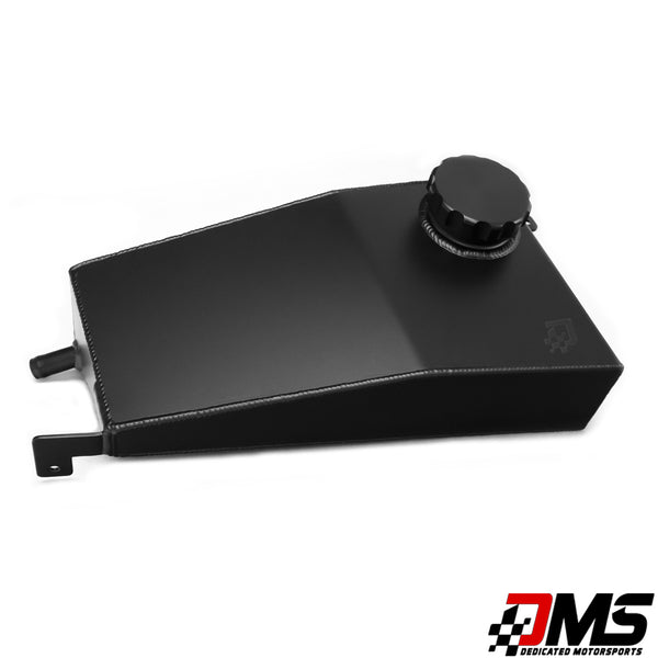
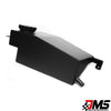
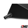
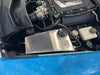
WEAPON-X: Eaton 1.7L Lid Spacer - Meth or Nitrous Options [Camaro Corvette CTS V, LT4]
Vendor: WEAPON-X Motorsports
SKU:

More info
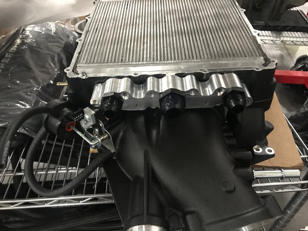
The new gen 5 LT1 and LT4 engines can be damaged when the high pressure fuel pump can't keep up. The LT4 cars over 650whp without an overdriven cam and 750whp with an overdriven cam can see this. The direct port meth kit with the lid spacer goes under the lid to allow 1 port per cylinder for even meth injection fuel distribution taking the strain off of the OEM fuel system while adding octane and cooling the charge post boost! The same can be done with spray bars for nitrous!
Features
- Get instant, reliable and safe horsepower
- T6061 Aluminum precision construction
- 12mm thickness
- Direct Port Meth or Nitrous spray bar options
Benefits
- More artificial plenum volume
- Lower IAT2s
- Direct port fueling for add on fuels when supplementing fuel pressure so there is no sketchy uneven distribution
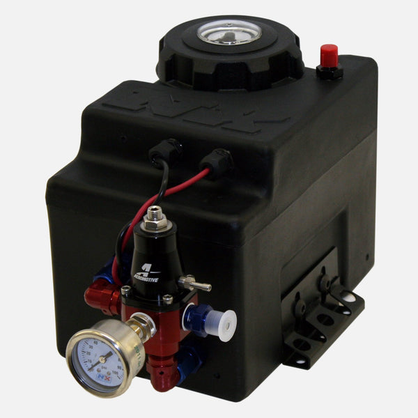
PRE/POST-BOOST METHANOL INJECTION KIT
"To provide a reliable methanol injection system solution for our customers application that meets or surpasses their expectations."With the flood of Injection systems on the market today, A little research and you will notice that most if not all provide systems based on a 50/50 mix, This is due in part to the higher cost of internal as well as external parts needed to hold up to 100% "safely". Perfect example is type of hoses used.When you purchase an Injection system from Alkycontrol your getting a product thats been tested time and time again by some of the fastest out there, be it cars, trucks, jet skis, airboats, and even a world record holding airplane. If it has a piston/rotor on boost, it will benefit from our injection system.The History on the Progressive Controller.A bit of history on the progressive controller and its development.Years ago, injection systems were marketed using a simple pressure switch, relay, nozzle, and pump. This is a very basic system and is still sold by many companies. From the beginning, this design had weaknesses. First, HOW MUCH liquid is needed by the engine to prevent detonation. What is needed in order to achieve a balance of system pressure vs. nozzle orifice sizing? Example: Let's say one needed 600 CC’s/minute at 15 PSI boost, then you would change the nozzle to achieve this setting. The problem is, how do you know you need the 600 CC’s when at 15 PSI boost? Enter the "trial and error" phase of system tuning...lots of guessing and nozzle changes.The next advancement was the use of a variable voltage controller which could be located in the "cockpit". Now, changes to pump voltage drive could occur. Reducing voltage drive reduced output and determining that 600 CC level could be accomplished in a more rapid fashion without changing “lots” of nozzles/jets.Great new feature with minimal experimentation...now the engine is detonation-free at 600CC's and 15 PSI boost, right? Wait, there's another new hurdle. When the boost needle hits 15 PSI, we realize there is a system "time-delay". When we tell the pump to activate, it's motor needs to spin, lines must fill, liquid passes through the nozzle, past the throttle body, past the intake valves and finally into combustion chambers. Solution? Activate the system at 10 PSI (or even less) to offset the time needed for liquid to reach the combustion chamber. Now, when 15 PSI is reached, the proper amount is being delivered under those conditions. Finally, all bases covered, right? Wrong! Now the issue is during a part throttle condition. When at 10 PSI, the motor will have far too much liquid at the lower boost level and will create surging and bogging at the activation set point.Ain't evolution fun? Now let's consider a "staged" setup where one small nozzle activates at 8 PSI and another at 13 PSI, so that at 15 PSI we would have the proper volume. Now we have adequate flow at the desired boost level...in a more gradual fashion. But wait! Due to the multiple pressure switches, solenoids, relays and wiring, the "plumbing" will be a nightmare when it comes to troubleshooting and/or service. Another issue...the above setup ONLY provided a specified amount at a specific boost level. In a turbo application it is possible for wastegate malfunctions to create boost levels much higher than the 15 PSI that was set. So, if the boost spiked to 20 PSI, we are only injecting enough to sustain 15 PSI. This could be followed by a “dead band” condition associated with mechanical switches, especially inexpensive types. Example: Let's say it activates at 8 PSI, but does not deactivate until under 3 PSI. Understand that pressure switches are mechanical in nature and each will have it's own characteristics. This is the reason we don’t use mechanical pressure switches to control key functions within the system...like activation.The fix for tuning issues associated with above systems was relatively simple. We created a way to develop a voltage "curve" based on boost pressure. The higher the boost, the more voltage sent to the pump, which creates higher pressure. This allows the system to activate early on, fill the lines at low pressures, while not affecting performance. This arrangement also provides the ability to continue add volume as manifold pressure is increased. This may sound easy, but here is where it gets a bit complex.The “curve” MUST be tailored to the engine’s volumetric efficiency. Simply put, having a simple activation/set point and maximum does not allow this to happen in every engine.Only recently have other companies begun to realize the need for changing the curve of their progressive controllers. Some now have added “Set” and “Max” settings. Recently, some have initiated thoughts about utilizing a microprocessor to control the injection process.Here is my take on that idea...As stated above, an injection system is comprised of a tank, pump, nozzle and electronics. The mechanical device in question is a relatively large pump with significant mass, capable of moving a lot of fluid at high pressure. Inherent is a rise and fall in pressure which takes time to achieve. Remember the "time-delay" issue earlier in this article (the system must activate earlier than needed)? The limiting speed factor in the system is the pump. A 64 MHZ processor will not spin the pump any faster or slower than a switch, meaning the system is only as fast as its slowest device. Abrupt changes to voltage will not cause abrupt changes to pressure. Rise and fall times are mechanical. Think of it like a garden hose with the handle open and someone opening and closing the valve abruptly. This is why there is confusion by those who think the systems work like fuel injectors that can be varied instantly. Also remember that the nozzle placement in front of the throttle body produces an additional "time delay". Redundant, important point...abrupt voltage variations CANNOT produce INSTANT delivery of liquid into the engine.In our case, simplicity was one of the goals. Now, what do we do that is different and why?Our main controller has three boxes, purposely designed for achieving various goals.First, the large pump draws considerable current. At 250 PSI on a 15 gallon per hour nozzle. the pump motor draws in excess of 12 amps and spikes will be even higher. Higher currents generate heat and this heat MUST be dissipated. The driver module on our controller is basically a very large heat-sink designed to keep heat away from the main controller PCB and its components and that is the reason it is mounted away from the PCB. It is rated at 45 amps and will sustain a constant high current load for hours without failure. The design is overkill and creates more work for us in building the unit, but the end result is a bullet-proof device. This assures zero heat stress to the main PCB and results in a reliable device. The main PCB and heat-sink are encased in a special polymer to keep parts from moving, similar to aftermarket ignition systems. An encased PCB will not develop bad connections due to vibration issues, such as racing an engine, suspension system, etc. Vibration is an important issue in a hostile environment like an automobile interior where temperatures can range from below freezing to "desert conditions". Controllers should be mounted in the interior...NOT in the engine compartment.Lastly, the 3rd box of our system allows for custom placement of the controls into flat panel surfaces or be mounted as is (installation flexibility).The aftermarket now pushes for smaller controllers (at the expense of reduced or eliminated heat sinking). You simply cannot transfer heat without an adequate heat sink. Designs from certain competitors mount the pump driver right on the PCB. Obviously, this makes for a smaller controller, but one subjected to tons of heat cycling. This is NOT an area where size should be reduced. Solder breaks down after repeated heating, cooling, heating, cooling, etc. Some systems don’t allow the ability to be switched on/off. In others, one cannot “test” the system. These are basic, important details lost in an effort to reduce costs. Rest assured, regardless of production costs, we strive to cover all areas, including surge suppression, reverse polarity protection, charging system malfunctions, wiring shorts, etc.
Post Boost addition kit:
LT4 Supercharger Lid Spacer
Qty 8 .4mm Check Valve Jets
Qty 8 Jet Adapter PN 806-357N
Qty 2 4 Port Distribution Manifolds
Qty 2 -4AN System adapters
14 Feet of black 4mm Nylon Tubing
![WEAPON-X: Thermostat Gen 5 Engine [Corvette Camaro CTS V, LT1 LT4 LT5]](http://weaponxmotorsports.com/cdn/shop/products/L310166914_900_grande.jpg?v=1571441471)
![WEAPON-X: Boost Chiller [Camaro Corvette CTS-V ]](http://weaponxmotorsports.com/cdn/shop/products/image_6025312d-55e6-4a35-9ab2-26a8a3bd78cb_grande.jpg?v=1571441792)
![WEAPON-X: Boost Chiller [Camaro Corvette CTS-V ]](http://weaponxmotorsports.com/cdn/shop/products/123_1_small.jpg?v=1571441792)
![WEAPON-X: Boost Chiller [Camaro Corvette CTS-V ]](http://weaponxmotorsports.com/cdn/shop/products/6A5A1878_small.jpg?v=1571441792)
![WEAPON-X: Boost Chiller [Camaro Corvette CTS-V ]](http://weaponxmotorsports.com/cdn/shop/products/6A5A1909_small.jpg?v=1571441792)
![WEAPON-X: Boost Chiller [Camaro Corvette CTS-V ]](http://weaponxmotorsports.com/cdn/shop/products/6A5A1950_small.jpg?v=1571441792)
![WEAPON-X: Boost Chiller [Camaro Corvette CTS-V ]](http://weaponxmotorsports.com/cdn/shop/products/6A5A2188_small.jpg?v=1571441792)
![WEAPON-X: Boost Chiller [Camaro Corvette CTS-V ]](http://weaponxmotorsports.com/cdn/shop/products/6A5A1958_small.jpg?v=1571441792)
![WEAPON-X: Boost Chiller [Camaro Corvette CTS-V ]](http://weaponxmotorsports.com/cdn/shop/products/6A5A1950_412db5de-40ad-4e3b-b08b-da7b50f5c1ae_small.jpg?v=1571441792)
![WEAPON-X: Boost Chiller [Camaro Corvette CTS-V ]](http://weaponxmotorsports.com/cdn/shop/products/6A5A1914_small.jpg?v=1571441792)
![WEAPON-X: Boost Chiller [Camaro Corvette CTS-V ]](http://weaponxmotorsports.com/cdn/shop/products/EzyWatermark180825120635835_small.png?v=1571441792)
![WEAPON-X: Boost Chiller [Camaro Corvette CTS-V ]](http://weaponxmotorsports.com/cdn/shop/products/image_3e3da9e2-8509-44de-8ec5-6150893e469a_small.jpg?v=1571441792)
![WEAPON-X: Boost Chiller [Camaro Corvette CTS-V ]](http://weaponxmotorsports.com/cdn/shop/products/20180702_174103_43e6546e-f379-4b53-b736-035c6d7f4aec_small.jpg?v=1571441792)
![WEAPON-X: Boost Chiller [Camaro Corvette CTS-V ]](http://weaponxmotorsports.com/cdn/shop/products/20180702_174053_e72d3d51-c6a6-472c-b71e-87fafdb28b30_small.jpg?v=1571441792)
![WEAPON-X: Boost Chiller [Camaro Corvette CTS-V ]](http://weaponxmotorsports.com/cdn/shop/products/20180627_102510_small.jpg?v=1571441792)
![WEAPON-X: Boost Chiller [Camaro Corvette CTS-V ]](http://weaponxmotorsports.com/cdn/shop/products/IMG00021_small.jpg?v=1571441792)
![WEAPON-X: Boost Chiller [Camaro Corvette CTS-V ]](http://weaponxmotorsports.com/cdn/shop/products/IMG00022_small.jpg?v=1571441792)
![WEAPON-X: Boost Chiller [Camaro Corvette CTS-V ]](http://weaponxmotorsports.com/cdn/shop/products/IMG00020_small.jpg?v=1571441792)
![WEAPON-X: Boost Chiller [Camaro Corvette CTS-V ]](http://weaponxmotorsports.com/cdn/shop/products/IMG_1669_small.JPG?v=1571441792)
![WEAPON-X: Boost Chiller [Camaro Corvette CTS-V ]](http://weaponxmotorsports.com/cdn/shop/products/IMG_1668_small.JPG?v=1571441792)
![WEAPON-X: Boost Chiller [Camaro Corvette CTS-V ]](http://weaponxmotorsports.com/cdn/shop/products/IMG_1667_small.JPG?v=1571441792)
![WEAPON-X: Boost Chiller [Camaro Corvette CTS-V ]](http://weaponxmotorsports.com/cdn/shop/products/IMG_1666_small.JPG?v=1571441792)
![WEAPON-X: Boost Chiller [Camaro Corvette CTS-V ]](http://weaponxmotorsports.com/cdn/shop/products/IMG_1665_small.JPG?v=1571441792)
![Dewitts: Competition Radiator [C7 Corvette, Z06, LT1 LT4]](http://weaponxmotorsports.com/cdn/shop/products/12440502_716640208437619_2810862004057475424_o_grande.jpg?v=1571441471)
![Dewitts: Competition Radiator [C7 Corvette, Z06, LT1 LT4]](http://weaponxmotorsports.com/cdn/shop/products/10636800_716640221770951_6293021767658802366_o_4b798ec7-9ab5-4caf-90bf-16ecfee0a146_small.jpg?v=1571441471)
![Dewitts: Competition Radiator [C7 Corvette, Z06, LT1 LT4]](http://weaponxmotorsports.com/cdn/shop/products/1139114m2_80cb67f3a905d1cf5ebf269299110c75f712d1b1_da75a7f1-7ba7-4b38-9d09-2a89dc5d1251_small.jpg?v=1571441471)
![Dewitts: Competition Radiator [C7 Corvette, Z06, LT1 LT4]](http://weaponxmotorsports.com/cdn/shop/products/IMG_2643_04f82b8f-be57-442d-8f13-05477dc3c376_small.jpg?v=1571441471)
![Dewitts: Competition Radiator [C7 Corvette, Z06, LT1 LT4]](http://weaponxmotorsports.com/cdn/shop/products/IMG_2644_5ab63efe-e62c-4882-9d99-8d75a2ec3f77_small.jpg?v=1571441471)
![Dewitts: Competition Radiator [C7 Corvette, Z06, LT1 LT4]](http://weaponxmotorsports.com/cdn/shop/products/IMG_2640_d21594bd-fc99-4539-b354-1f8d05a83e93_small.jpg?v=1571441471)
![Dewitts: Competition Radiator [C7 Corvette, Z06, LT1 LT4]](http://weaponxmotorsports.com/cdn/shop/products/IMG_2642_035b5743-dfc2-4aa8-acef-55804b090b6b_small.jpg?v=1571441471)
![WEAPON-X: Track Attack Heat Exchanger [C7 Corvette, Z06, LT4]](http://weaponxmotorsports.com/cdn/shop/products/IMG_1567_grande.jpg?v=1571441471)
![WEAPON-X: Track Attack Heat Exchanger [C7 Corvette, Z06, LT4]](http://weaponxmotorsports.com/cdn/shop/products/IMG_1571_small.jpg?v=1571441471)
![WEAPON-X: Track Attack Heat Exchanger [C7 Corvette, Z06, LT4]](http://weaponxmotorsports.com/cdn/shop/products/IMG_1572_small.jpg?v=1571441471)
![WEAPON-X: Track Attack Heat Exchanger [C7 Corvette, Z06, LT4]](http://weaponxmotorsports.com/cdn/shop/products/IMG_1573_small.jpg?v=1571441471)
![WEAPON-X: LT4 Cooling Manifold Adapters [C7 Corvette Z06, Camaro ZL1, CTS V3, LT4]](http://weaponxmotorsports.com/cdn/shop/products/IMG_9733_grande.JPG?v=1602597357)
![WEAPON-X: LT4 Cooling Manifold Adapters [C7 Corvette Z06, Camaro ZL1, CTS V3, LT4]](http://weaponxmotorsports.com/cdn/shop/products/IMG_0201_small.JPG?v=1602597357)
![WEAPON-X: LT4 Cooling Manifold Adapters [C7 Corvette Z06, Camaro ZL1, CTS V3, LT4]](http://weaponxmotorsports.com/cdn/shop/products/IMG_0892a_small.jpg?v=1602597357)
![WEAPON-X: LT4 Cooling Manifold Adapters [C7 Corvette Z06, Camaro ZL1, CTS V3, LT4]](http://weaponxmotorsports.com/cdn/shop/products/IMG_0731_d3b01fa9-5e52-4622-a1d1-7e01a968e2d0_small.JPG?v=1602597357)
![WEAPON-X: LT4 Cooling Manifold Adapters [C7 Corvette Z06, Camaro ZL1, CTS V3, LT4]](http://weaponxmotorsports.com/cdn/shop/products/1E94C448-8E74-42FD-8771-851C30985F22_small.JPG?v=1602597357)
![WEAPON-X: LT4 Cooling Manifold Adapters [C7 Corvette Z06, Camaro ZL1, CTS V3, LT4]](http://weaponxmotorsports.com/cdn/shop/products/IMG_0200_small.JPG?v=1602597357)
![WEAPON-X: LT4 Cooling Manifold Adapters [C7 Corvette Z06, Camaro ZL1, CTS V3, LT4]](http://weaponxmotorsports.com/cdn/shop/products/IMG_0202_small.JPG?v=1571441785)
![WEAPON-X: LT4 Cooling Manifold Adapters [C7 Corvette Z06, Camaro ZL1, CTS V3, LT4]](http://weaponxmotorsports.com/cdn/shop/products/IMG_0203_small.JPG?v=1571441785)
![WEAPON-X: LT4 Cooling Manifold Adapters [C7 Corvette Z06, Camaro ZL1, CTS V3, LT4]](http://weaponxmotorsports.com/cdn/shop/products/IMG_0378_small.JPG?v=1571441785)
![WEAPON-X: LT4 Cooling Manifold Adapters [C7 Corvette Z06, Camaro ZL1, CTS V3, LT4]](http://weaponxmotorsports.com/cdn/shop/products/IMG_0832_small.JPG?v=1571441785)
![WEAPON-X: LT4 Cooling Manifold Adapters [C7 Corvette Z06, Camaro ZL1, CTS V3, LT4]](http://weaponxmotorsports.com/cdn/shop/products/IMG_0833_small.JPG?v=1571441785)
![WEAPON-X: LT4 Cooling Manifold Adapters [C7 Corvette Z06, Camaro ZL1, CTS V3, LT4]](http://weaponxmotorsports.com/cdn/shop/products/IMG_0834_small.JPG?v=1571441785)
![WEAPON-X: LT4 Cooling Manifold Adapters [C7 Corvette Z06, Camaro ZL1, CTS V3, LT4]](http://weaponxmotorsports.com/cdn/shop/products/LT4_adapters_installed_small.jpg?v=1571441785)
![WEAPON-X: Meth 4 Gallon Tank Bracket [ATS V, Camaro, CTS V, Corvette]](http://weaponxmotorsports.com/cdn/shop/products/20170523_201424_a76d6fe1-57db-46ec-a144-83d3f82a2ef4_grande.jpg?v=1571441793)
![WEAPON-X: Meth 4 Gallon Tank Bracket [ATS V, Camaro, CTS V, Corvette]](http://weaponxmotorsports.com/cdn/shop/products/20170523_201427_bcd4b6b4-aa72-4824-8c69-d79e7d37c2f5_small.jpg?v=1571441793)
![WEAPON-X: Meth 4 Gallon Tank Bracket [ATS V, Camaro, CTS V, Corvette]](http://weaponxmotorsports.com/cdn/shop/products/IMG_7994_abdf9d95-96a7-445f-ac8e-9632013551c5_small.jpg?v=1571441793)
![WEAPON-X: Meth 4 Gallon Tank Bracket [ATS V, Camaro, CTS V, Corvette]](http://weaponxmotorsports.com/cdn/shop/products/IMG_8003_d32b3f82-d915-428b-bbb3-3515b24d5c2d_small.jpg?v=1571441793)
![WEAPON-X: Meth 4 Gallon Tank Bracket [ATS V, Camaro, CTS V, Corvette]](http://weaponxmotorsports.com/cdn/shop/products/IMG_8012_7dfcbe17-a84d-4a98-8ce1-7f2cc269d590_small.jpg?v=1571441793)
![WEAPON-X: Heat Exchanger Expansion Tank [C7 Corvette Z06, LT1 LT4]](http://weaponxmotorsports.com/cdn/shop/products/image1_b9077952-c418-446e-9c40-354a291d78ac_grande.jpeg?v=1571441794)
![WEAPON-X: Heat Exchanger Expansion Tank [C7 Corvette Z06, LT1 LT4]](http://weaponxmotorsports.com/cdn/shop/products/image2_small.jpeg?v=1571441794)
![WEAPON-X: Heat Exchanger Expansion Tank [C7 Corvette Z06, LT1 LT4]](http://weaponxmotorsports.com/cdn/shop/products/image3_small.jpeg?v=1571441794)
![Dewitts: Engine Oil Cooler Kit [C7 Corvette, Z06, LT1 LT4]](http://weaponxmotorsports.com/cdn/shop/products/8119001E_1024x1024_27ee1ae5-39b2-4eed-a343-54967252ce30_grande.jpg?v=1571441590)
![WEAPON-X: The Cooling Kit [C7 Corvette, LT1 LT4]](http://weaponxmotorsports.com/cdn/shop/products/image_1_grande.png?v=1571441394)
![WEAPON-X: The Cooling Kit [C7 Corvette, LT1 LT4]](http://weaponxmotorsports.com/cdn/shop/products/image3_1024x1024_e4f232f8-be33-4d86-acf0-342e1ad7a15e_small.jpg?v=1571441394)
![WEAPON-X: The Cooling Kit [C7 Corvette, LT1 LT4]](http://weaponxmotorsports.com/cdn/shop/products/1139114m2_80cb67f3a905d1cf5ebf269299110c75f712d1b1_1024x1024_5cdfbacd-927a-4aad-9e42-81610bd558d2_small.jpg?v=1571441394)
![WEAPON-X: The Cooling Kit [C7 Corvette, LT1 LT4]](http://weaponxmotorsports.com/cdn/shop/products/123_1_grande_5cb23932-b6e2-497f-bdde-255bc980e00f_small.jpg?v=1571441394)
![WEAPON-X: The Cooling Kit [C7 Corvette, LT1 LT4]](http://weaponxmotorsports.com/cdn/shop/products/6A5A1878_1024x1024_f4a4658c-cd3c-4828-8bc5-0e48a12123fd_small.jpg?v=1571441394)
![WEAPON-X: The Cooling Kit [C7 Corvette, LT1 LT4]](http://weaponxmotorsports.com/cdn/shop/products/2019-02-08_12.45.17_small.jpg?v=1571441394)
![FP: Thermal Reduction Plates [C7 Corvette Z06, Camaro ZL1, CTS V, LT4]](http://weaponxmotorsports.com/cdn/shop/products/Spacerengine_zps091cb09d_grande.jpg?v=1571441471)
![FP: Thermal Reduction Plates [C7 Corvette Z06, Camaro ZL1, CTS V, LT4]](http://weaponxmotorsports.com/cdn/shop/products/IMG_0205-2_zps1fe5f8a7_98281ad7-6d6e-4b4d-84cc-33cdcefc1157_small.jpg?v=1571441471)
![FP: Thermal Reduction Plates [C7 Corvette Z06, Camaro ZL1, CTS V, LT4]](http://weaponxmotorsports.com/cdn/shop/products/11247566_755295047922367_285142003_n_small.jpg?v=1571441471)
![FP: Thermal Reduction Plates [C7 Corvette Z06, Camaro ZL1, CTS V, LT4]](http://weaponxmotorsports.com/cdn/shop/products/IMG_0202-3_zps56af7ed0_small.jpg?v=1571441471)
![Granatelli: Heat Exchanger Expansion Tank [C7 Corvette Z06, LT4]](http://weaponxmotorsports.com/cdn/shop/products/ExpansionTank_jpeg_grande.jpg?v=1571441394)
![Granatelli: Heat Exchanger Expansion Tank [C7 Corvette Z06, LT4]](http://weaponxmotorsports.com/cdn/shop/products/ExpansionTank2_small.jpg?v=1571441394)
![Granatelli: Heat Exchanger Expansion Tank [C7 Corvette Z06, LT4]](http://weaponxmotorsports.com/cdn/shop/products/ExpansionTank3_small.jpg?v=1571441394)
![Fasterproms: 1.5G Heat Exchanger Expansion Tank [C7 Corvette, Z06 LT4]](http://weaponxmotorsports.com/cdn/shop/products/11236042_758412617590842_1535569564_n_grande.jpg?v=1571441471)
![Fasterproms: 1.5G Heat Exchanger Expansion Tank [C7 Corvette, Z06 LT4]](http://weaponxmotorsports.com/cdn/shop/products/2015-chevrolet-corvette-zo6-lt4-engine_small.jpg?v=1571441471)
![Fasterproms: 1.5G Heat Exchanger Expansion Tank [C7 Corvette, Z06 LT4]](http://weaponxmotorsports.com/cdn/shop/products/2015-chevrolet-corvette-zo6-fasterproms-ic-tank_small.jpg?v=1571441471)
![Fasterproms: 1.5G Heat Exchanger Expansion Tank [C7 Corvette, Z06 LT4]](http://weaponxmotorsports.com/cdn/shop/products/IMG_0205-2_zps1fe5f8a7_small.jpg?v=1571441471)
![WEAPON-X: LT4 HD Intercooler Bricks [Camaro ZL1, C7 Corvette Z06, CTS V, LT4]](http://weaponxmotorsports.com/cdn/shop/products/IMG_1093_grande.jpg?v=1571441785)
![WEAPON-X: LT4 HD Intercooler Bricks [Camaro ZL1, C7 Corvette Z06, CTS V, LT4]](http://weaponxmotorsports.com/cdn/shop/products/IMG_1091_small.jpg?v=1571441785)
![Big 3 Racing: 2 Gallon Heat Exchanger Expansion Tank [C7 Corvette, Z06 LT4]](http://weaponxmotorsports.com/cdn/shop/products/zo6_7dc30a99-10d4-4f9e-9833-37c1c858e7c9_grande.jpg?v=1571441395)
![WEAPON-X: Eaton 1.7L Lid Spacer - Meth or Nitrous Options [Camaro Corvette CTS V, LT4]](http://weaponxmotorsports.com/cdn/shop/products/image2_175e7879-ff74-4a87-b447-ef69ce78f396_small.jpg?v=1571441394)
![WEAPON-X: Eaton 1.7L Lid Spacer - Meth or Nitrous Options [Camaro Corvette CTS V, LT4]](http://weaponxmotorsports.com/cdn/shop/products/cts_v_alky_control_1024x1024_4b12a509-0502-47a1-86c5-3552ed942f58_small.jpg?v=1571441394)
![WEAPON-X: Eaton 1.7L Lid Spacer - Meth or Nitrous Options [Camaro Corvette CTS V, LT4]](http://weaponxmotorsports.com/cdn/shop/products/photo_3__44468.1353812148.1280.1280_1024x1024_09662445-0de5-43d8-9fc0-331741bfdc35_small.jpg?v=1571441394)
![WEAPON-X: Eaton 1.7L Lid Spacer - Meth or Nitrous Options [Camaro Corvette CTS V, LT4]](http://weaponxmotorsports.com/cdn/shop/products/image_1024x1024_5515e871-a38f-47a6-8b65-0b1463df3632_small.jpg?v=1571441394)

![PWR C&R: LT4 HD Intercooler Bricks [Camaro ZL1, C7 Corvette Z06, CTS V, LT4]](http://weaponxmotorsports.com/cdn/shop/products/CR-UC-SPI009B-LT4-Brick-Flat-scaled_1518x_df5e7375-b31a-4b28-8d07-2d6515784e5f_grande.jpg?v=1607025820)
![PWR C&R: LT4 HD Intercooler Bricks [Camaro ZL1, C7 Corvette Z06, CTS V, LT4]](http://weaponxmotorsports.com/cdn/shop/products/LT4-Gen-2-Slanted-Intercooler-Bricks-scaled_1590x_3c5854ca-44c8-4adf-aa25-797a486e8dc5_small.jpg?v=1607025821)
![Nitrous Express: NOS Plate Kit [C7 Corvette, GS Z06 ZR1 LT1 LT4 LT5]](http://weaponxmotorsports.com/cdn/shop/products/20938-10_grande.jpg?v=1571441054)
![WEAPON-X: Whipple LT1 LT4 Cooling Adapters [Camaro Corvette CTS V, LT]](http://weaponxmotorsports.com/cdn/shop/products/image_9b97fe76-8750-465b-879a-0cf66b6345e7_grande.jpg?v=1571441896)
![WEAPON-X: Whipple LT1 LT4 Cooling Adapters [Camaro Corvette CTS V, LT]](http://weaponxmotorsports.com/cdn/shop/products/image_0e81af22-d0a3-4605-a87d-2b2153c0fe95_small.jpg?v=1571441896)
![Ron Davis: Radiator [C7 Corvette, Z06, LT1 LT4]](http://weaponxmotorsports.com/cdn/shop/products/1-16CVC7_grande.jpg?v=1571441146)